Assembly Guide - Circuit Board Assembly
Assembly Guide - Circuit Board Assembly
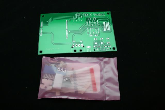
Next up we will be assembling the circuit board. You will need a good soldering iron, solder and a pair of small wire cutters.
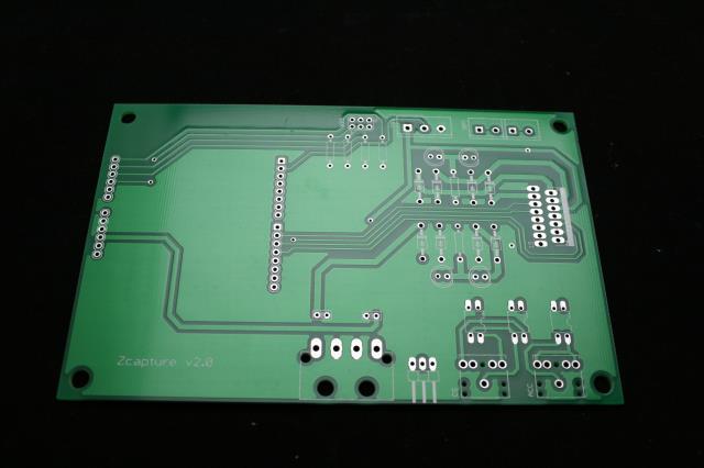
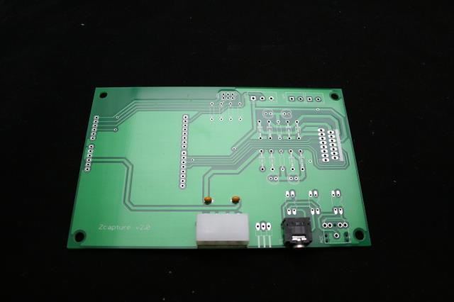
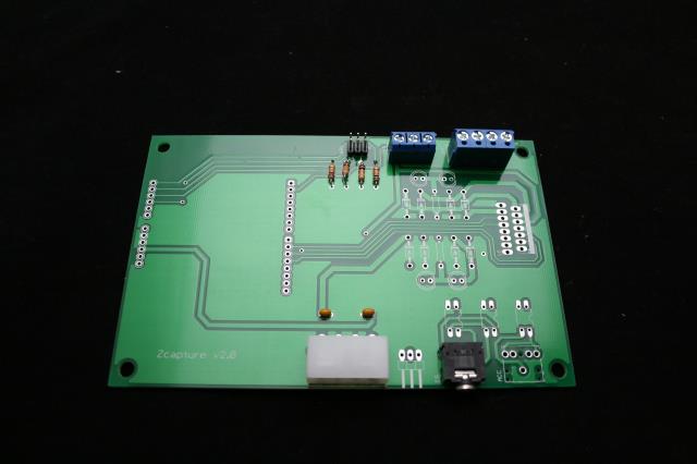
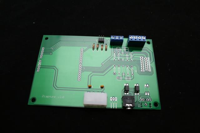
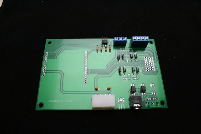
Here we have the circuit board. We will be populating components generally from shortest to tallest to make it easy for you to solder this board.
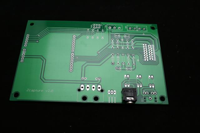
Step one is to install our stereo jack. As shown. Note there are two possible positions here; use the left position as shown. The other jack is if you want to hack or tinker with adding another jack.
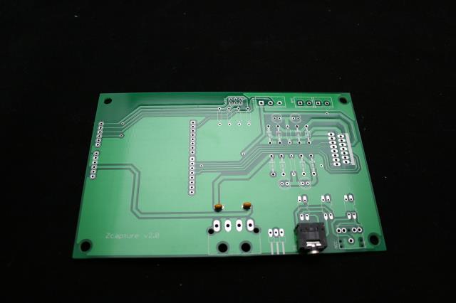
Next we will be adding our two capacitors shown in the middle of the board.
Next we will be adding the Molex power connector.
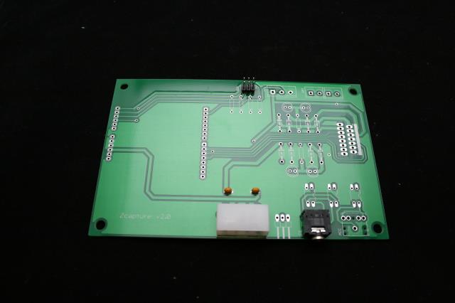
Here we will add the 6 pin terminal.
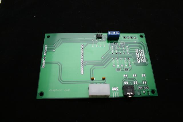
Next we will add our screw terminal jack that has 3 positions on it. Make sure the holes on the side of the terminal are facing the edge of the board.
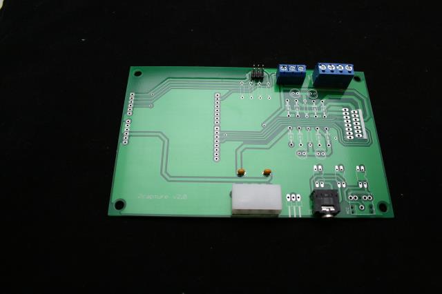
Next we will add the larger screw terminal jack that has 4 positions on it. Make sure the holes on the side of the terminal are facing the edge of the board.
Next we will add the resistors to the board. Not all 4 of them are required, but for tinkering sake we have included them.
Next we will add our optical isolators. These small microchip appearing devices are positioned directly above our stereo jack as pictured. Do not place it in the right most spot.
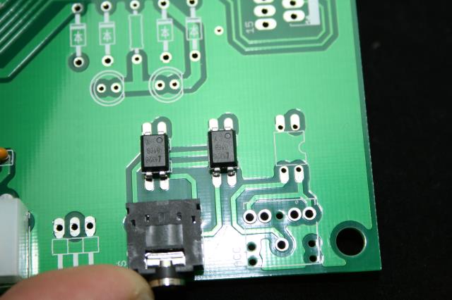
Here is a close up look at the optical isolators. Note the dot in the top right corner. This item must be place the same way or it wont work.
Important!
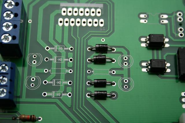
Next we will be adding the diodes to the board. Again this component must be added the right direction. Note the white band on the pictures on the board and the band around the diode. All diodes will face the same direction.
Important!
Next we will add the driver ship to the board. Note the orientation is the same as pictured on the board.
Important!
Here we can see the diodes added to the board
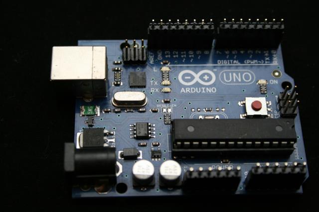
Now we have our final step, to make it a lot easier, add the pins to the Arduino as shown. The longer length will be inside the Arduino headers and the shorter ends exposed. This will help insure alignment of this step.
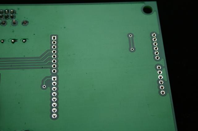
Here we can see the pins poking out the back side of the board.
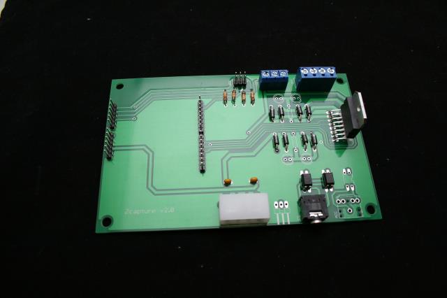
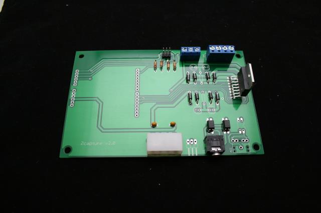
Here we have our finished circuit board.
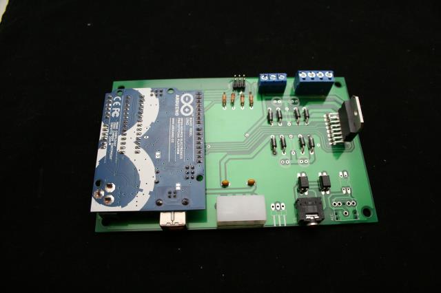
And here we can see the board with the Arduino mounted. We will need to remove this to mount the board to the chassis, but it looks awful cool…